appnext

Tampilkan postingan dengan label homemade. Tampilkan semua postingan

Senin, 21 Maret 2016

Quickie: brake pipe retaining tab

Thought I would throw out a bite-sized update in lieu of a more substantial post, as my garage time has been rather short of late...

As you may notice in the peripheral of the photos below (the last couple in particular), I have been laboriously cleaning up all the plug welds from around the edge of the pans recently. However, it is taking me quite a bit of time to do, so to break up the monotony I thought I would repair one of the little retaining tabs that fasten the brake pipe in place alongside the chassis tunnel. These were originally spot welded on and not really designed to withstand a lot of fatigue. So, it was no surprise that one of these pieces came off earlier on in the resto. Making a fresh one seemed to be the best way forward. I flattened the old original piece in a vice so I could take a few dimensions which I jotted down. I then cut a piece of fresh steel of the same thickness (old tab on the left, newly cut tab on the right):


Drilled an 8mm hole for plugging and bent up the bottom to allow for the brake pipe to slide underneath. This will eventually be bent back around the brake pipe once positioned. Gave it a lick of zinc primer:


To ensure a flush fit to the tunnel I gently curved the upper part of the piece by hand to match the contour of the tunnel. I then lined it up:


Finished off by plug welding into place, dressed the weld and coated with zinc primer (the usual process):


Selasa, 16 Februari 2016

Pedal reinforcement plate

I needed to recreate the pedal reinforcement plate the I absent mindedly cut though thinking that it was part of an old crusty patch repair. Using a piece of 5mm flat bar I transferred the dimensions from the drawing I created and used the remains of the original to double check accuracy. After some trimming and grinding I had the basic shape sorted:


Once I had located the exact position of the mount holes I began drilling them out on the pillar drill, firstly with a pilot hole:


I then moved up to the 6.80mm tapping bit that I ordered online specifically for this task:


Then added the treads using an M8 x 1.25 tap to match the original. It really pays to go slow here and use tapping compound:


I needed to add more material to the top of the naps hat flange so that the overall thickness approached that of the pedal reinforcement plate (wish I would have thought of this at the time I was repairing this section). To do this I clamped some copper underneath the section and progressively added weld to the top, which I later ground flush:


To assist with getting good weld penetration I chaffered the edges of the pedal reinforcement plate and set a 1mm root gap at the bottom (with corresponding 1mm root face):


Offered up, fitting finessed and ready for welding:


I practiced on some scraps first as I have never welded steel this thick and I really only had one shot of getting it right. Welder settings needed to be cranked up and I also fitted my welder with thicker 0.8mm wire. Blew a couple of fuses whilst experimenting with the setup! This is the finished product after a wire brush and zinc priming:


Top side sanded flush along the weld seams and ready for final fitting of the floor pan half. Fitted a couple of new M8 8.8 bolts for good measure:


Happy with that!

Sabtu, 08 Agustus 2015

Spine plate repair section

A little repair patch that I fabricated:


Liberally sprayed the inside of the flanges with some zinc rich weld through primer:


The piece offered up and clamped in place ready for welding:


Started with a few spaced out tack welds and then continued to fill the spaces in-between until it was a solid weld:


Welds ground down and dressed with a quick lick of primer just to keep things fresh. Not bad if I do say so myself:


Rabu, 24 Juni 2015

Napoleon fix-up (part 1)

A turning point has been reached as things are now very slowing starting to go back together! Because this blog post documents the first significant metalwork repair on the car, I have opted to covered it in step-by-step detail (don't worry, im not going to be as obsessive about describing every single minor repair in the future!). I shall publish this task in several parts as I progress, just to make it more digestible. 

Enough of the intro, lets jump into the action.... 

Repairing the Naps hat from the previous 'balls-up' has been weighing on my mind ever since the incident. You may recall from this previous post that I had ended up with a rather large gap between the old metalwork and the repair section due to poor judgment on my part. Since that time I have attempted to make various repair sections, but the arbitrary angles have caused nothing but frustration and poor alignment. I needed to simply things and approach this from a different angle (pun not intended). So, I decided to recut the remaining naps hat at a 90 degree angle to the diagonally sloping top edge. Here is the proposed angle marked with gaffer tape:


Checking for accuracy using a set square;


Once cut and neatened up I was confident that I had an angle that I could trust. It was a known quantity:


The main reason that I failed initially was that I had not focused on keeping the bottom edge of the repair straight and true. So, I figured that making a jig was the way to go this time. Essentially, I joined 2 pieces of scrap box section together using spot welds on one side and beads on the other. With the beads ground down and a lick of primer added I had a nice flat area:


I then made a paper template stencil with the bolt holes carefully mapped out to match the factory dimensions (with additional cross-hairs to visually assist with alignment). Also marked out some guides for aligning the jig with the chassis tunnel:


A quick spray of red primer to contrast against the grey:


....and the jig was good to go:


With the jig clamped into place on the chassis, I was provided with a solid foundation to work from. I trimmed up the end of the repro panel (again at 90 degrees to the sloping diagonal) and positioned it on the jig, clamping it into place. This allowed me to accurately assess the missing gap that I needed to fabricate:


Once measured up I cut out the repair section from fresh 2mm thick steel. Before bending the patch into shape, I knocked up a diy former to ensure that the outer profile of the piece would accurately match the original. I then put the whole lot into a vice and when I was sure everything was lined up correctly I proceeded to progressively tap the piece over with a rubber mallet:


 This created a good 90 degree bend with a suitable bend radius:


The fabricated piece all clamped up, aligned and ready for the welding to commence:


After countless hours playing with the settings on my new welder to ensure adequate penetration, I was finally confident to make the first tack weld of this resto - a significant milestone:


All of the tacks in place just prior to filling in the spaces in-between with a series of stich welds. To mitigate any heat warping, I filled up my compressors and used the air gun to blast a jet of cool air onto the hot welds:


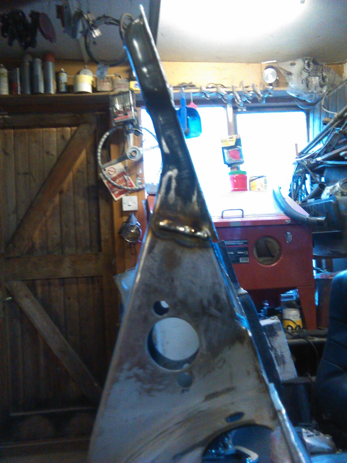
Once it was all fully welded up I carefully ground the welds down dressed the area to make the new section blend seamlessly. Also rough cut the excess away from the bottom edge of the new piece:


Lining up the end section cut from the repro panel:


and here it is all welded in:


....and ground down nice & flush:


Seeing this section coming together has been really motivating and has boosted my confidence no end. You know, I reckon I can do this! 

Coming up in Part 2: I shall be cutting the bottom sections flush with the jig ready to accept newly fabricated flanges, drilling a few holes and more... Oooooh, the suspense!

Selasa, 22 Juli 2014

Modifications to my blasting rig

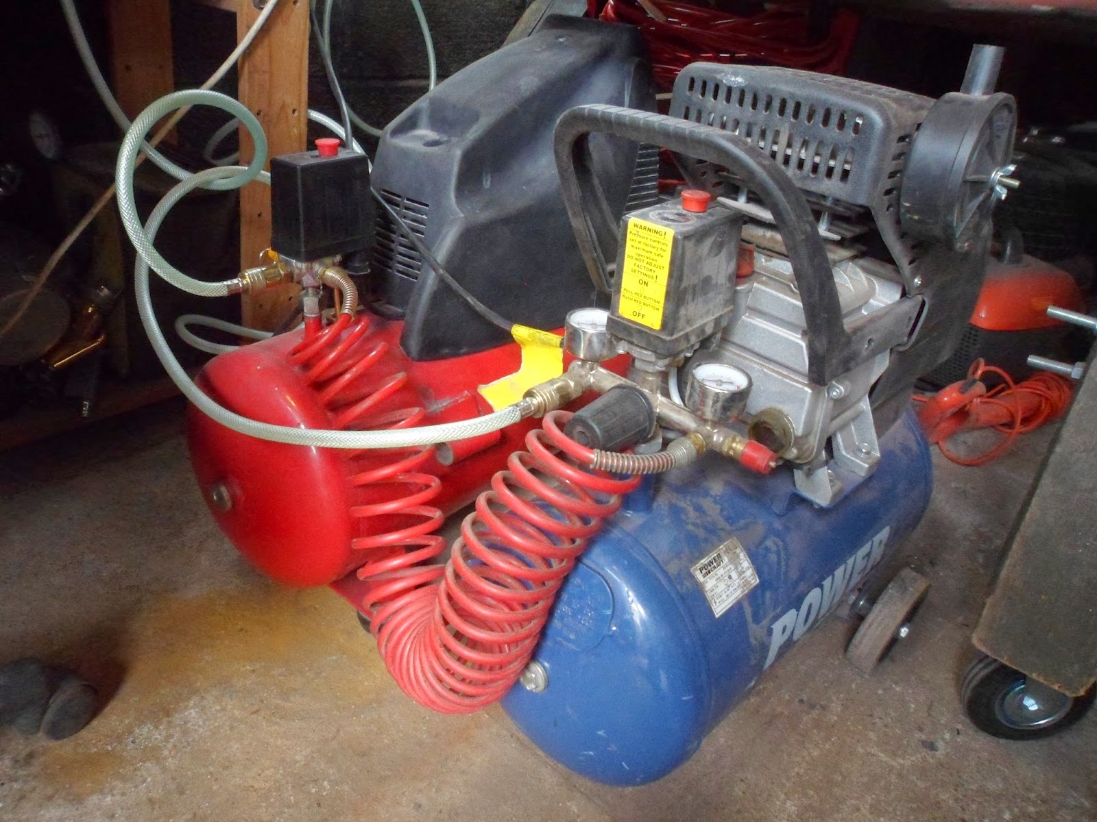
I have finally got myself a second compressor at a bargain price, whoooo! �although I later found that it had a cracked air manifold with a bodged repair, boooo! �thankfully it was very cheap to replace the whole damaged piece. Anyway, after lots of head scratching I linked them up to each other as shown in the photo below:


With both compressors running in tandem I can pretty much blast constantly without ever dropping below 100psi. The only thing to be considered is the duty cycle of the compressors, particularly as they heat up quick! So far I have been blasting for about 10mins and then take a break (well, finding something else to do) for 10mins to allow the compressors to cool down. It is a huge improvement, but blasting is still a slow process with a relatively humble set-up such as this!

To take care of the dust cloud issue, which fills the cabinet within 5mins of blasting, I initially attached a domestic vacuum cleaner to the outlet. However, it proved to be far too powerful for this cabinet and almost sucked the rubber gloves off of the mountings! So, after some playing I devised a rudimentary solution using an old 12V pump (the camping type, typically used to inflate air beds) connected to the inlet hole. The idea being that the pump creates higher air pressure inside the cabinet and as physics tells us, the air will move (along with the dust) to an area of lower pressure, via the filtered outlet in this case. 


It may appear to be too small to make any noticeable improvement, but I found that it significantly speeds up the rate that the dust clears. On the outside of the filtered outlet I have added a cardboard tube with one end cut at an angle. This is end is placed directly over the outlet hole with the other end faces out of the garage window behind the cabinet. In other words it is a cardboard exhaust pipe and it makes a huge difference in preventing the extracted dust from accumulating in the garage.


At the moment everything is held in place with copious amounts of gaffer tape and although it would be great to fabricate something more permanent, I really just want to get blasting, so sod it - I am going to leave it rough and ready!

Rabu, 19 Juni 2013

Pan rotisserie (and other short stories)


Most of the past couple of weeks have been spent organising and equipping the new garage as well as clearing out the old one. I have now built a workbench, layed out a tool board, put up shelves etc. In between these tasks I have made time to continue cleaning up the chassis. I decided to start by removing the rough cut floor pan remnants away from the supporting lip that runs along either side of the tunnel. Initially I was using my air chisel, but found it to be quite severe and could easily damage areas of the old metal that I was keen to save. So, I opted to do it by hand using pry bars, long screwdrivers and hand chisels. I basically worked my way around the parimeter popping off the spot welds one by one:


In theory this should have been a quick win, but the reality was that it took 10 times as long owing to all the past botched repairs and inconveniently welded parts that had be stuck together in areas that should never have been joined. For example; one seat runner was welded to the tunnel rather than spot welded to floor pan.... and then there were repair plates that had been placed over severely rusted areas without the old rot being cut out first.... Anyway, little by little I made progress and took the excess metal off cleanly. 
 
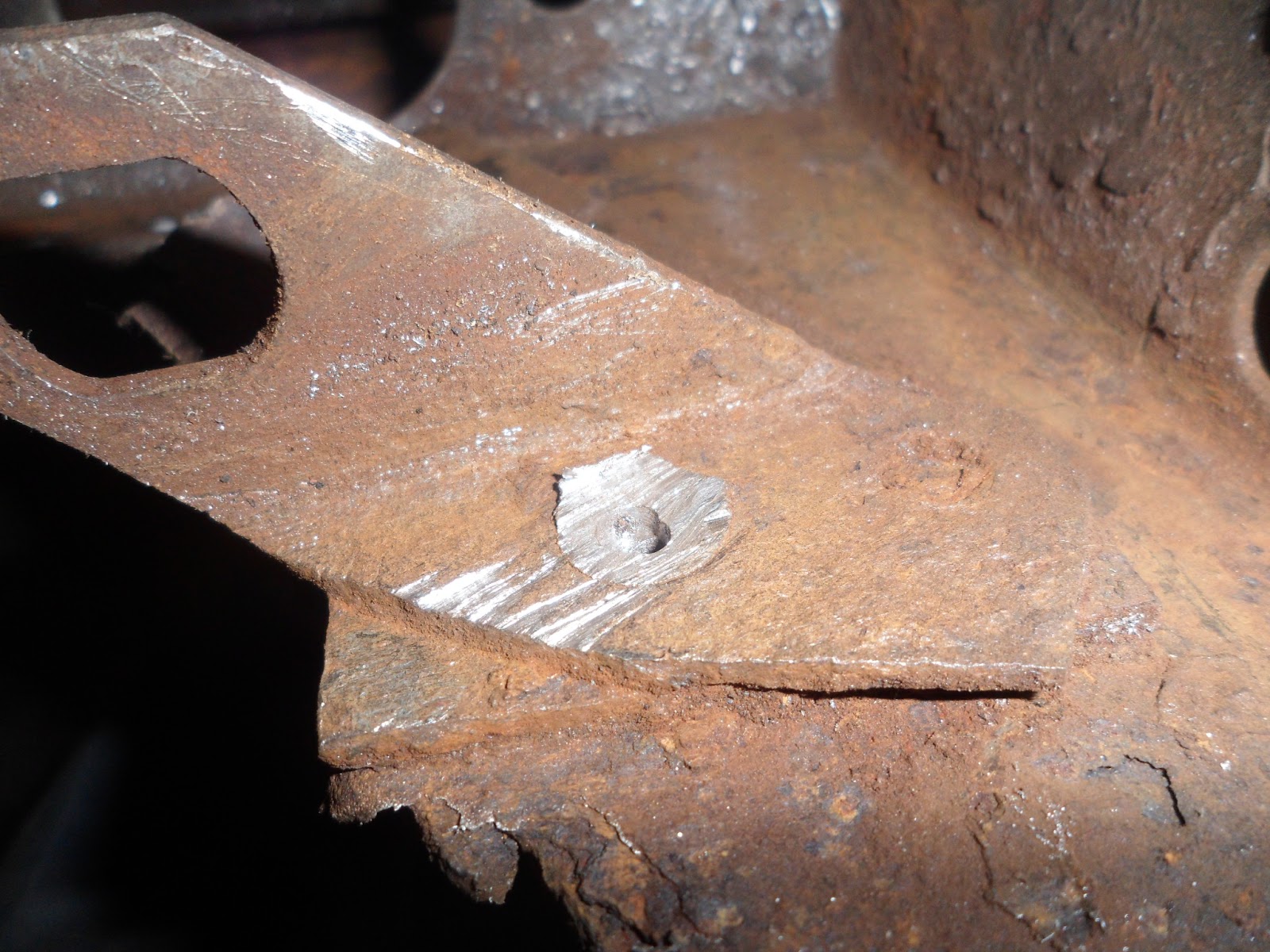
Next up was a seized bolt that was holding the pedal mounts in place. I tried everything to get it turning � penetrating oil, heat, wire brushing � but the stubborn little thing did not want to budge! I felt the only way forward was to carefully drill it out. I started by centre punching the top of the nut and then drilled a small pilot hole. Using a wider drill bit I slowly widened the hole:


I then switched to my trusty electric saw and made a horizontal cut to get rid of the overhanging sides of the bolt:


When I got the cut flush I simply tapped the piece out:


It took some time a patience, but I was pleased with the outcome


The next task will be to wire brush the old paint, underseal and dirt off of the framehead and bottom plate so that I can assess how much metal work needs replacing. To make this impending task easier I decided to build a simple wooden pan rotisserie so that I could reposition and rotate the chassis as desired without breaking my back each time. I constructed the framework entirely from scrap timber that had been left by the previous occupant and thanks to the fact that I can now operate my power tools (electricity, beautiful electricity, I am loving all 240 volts of it!) I had it built in no time. The only problem I came accross was how to secure the rear frame horns to a pivot piece. The original bolts were simply not long enough to pass through a piece of wood and reach the internal threads. I looked about for equivalent bolts of the same diameter with a longer shaft, but they were either ridiculously expensive or had a different screw profile. I ultimately concluded that trying to force a modern bolt to fit could lead to the threads becoming deformed or weakened. My garage neighbor, Tony, then came up with a simple solution; take a thick length of dowell (slightly oversized), taper the end and screw it in so that it threads itself:

I was dubious at first, but decided to give it a go and was impessed with how sturdy it seemed. I added a piece in on the other side and cut the dowell to a desired length. I then gently tapped on the connecting wooden pivot piece using a rubber mallet. 


This joint should hold well for the duration of the pan restoration. 


Here is the finished product with braked swivel casters added and the pan mounted up:


Simple and effective! Now I am ready for the fun to begin....