appnext

Senin, 27 Juli 2015

Napoleon fix-up (part 2)

Using a strip of gaffer tape and spray paint, I marked up a suitable recess for my fabricated replacement flanges, ensuring that all the pitted metal on the inner side would be removed:


All cut and squared up:


I made some 90 degree flanges out of 2mm sheet. Took me a couple of attempts to get it right. Matching the curve radius was a challenge as it is gentle and not sharp. The solution was to bend them around a curved section of the left-over scraps of the repro Naps Hat:


I then finessed them to fit using my bench grinder. Trim, check, trim, check. One side aligned with the help of the trusty jig:


Fully welded and the weld dressed:


Same process repeated on the other side:


I got pretty good penetration for the most part, but there were small areas inside the naps hat that the weld had not reached. For piece of mind I added some reinforcing welds on the inside. These will not be seen and just add a little bit more strength: 


Here is the flange trimmed up and the welds ground level:


To get the correct placement of the hole(s) for the brake pipe to pass through, I cut out the corresponding sections from the repro panel to use as a template:


I then clamped them into place, aligning the master cylinder holes (which did not match up at all well, so I am glad that I have retained the original factory holes!):


I then drilled the holes out to just below the required size. I then used a cylindrical grinding stone mounted in the Dremmel tool to neatly widen the hole to the correct size using the repro section template to guide me:


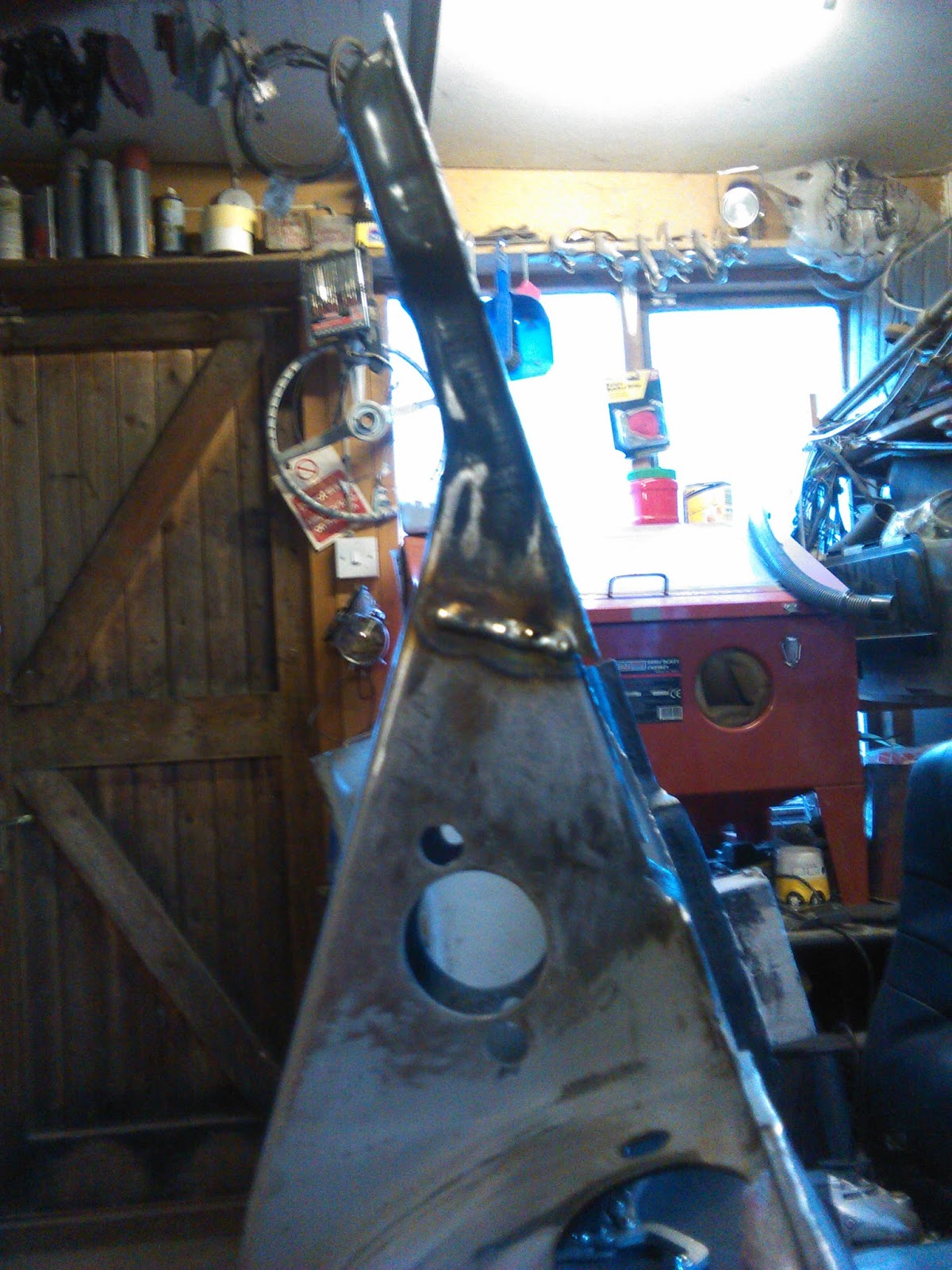
And finally (drum roll please), the drivers side of Naps Hat completed and given a lick of primer:


It looks pretty sweet but is not totally perfect. There are a few areas where it appears that the alignment is slightly skewed (minor heat warping perhaps?), but I am optimistic that this will straighten up once the frame head bottom plate and floorpans have been welded into place. 

Coming up in Part 3: I repeat the whole process on the passengers side...

Selasa, 07 Juli 2015

New fuel line! ...and other miscellaneous repairs

The internal captive nut holder which the accelerator 'guide-tube-backing-plate-thingy' and outer cover plate attaches to (at the front end of the tunnel) had partially rusted out along its bottom edge. In its corroded state the captive nut was loose and close to being ineffective, so a functional repair was required. I started by straightened up the bottom edge of the affected area using the small grinding stone mounted in a Dremel tool. I then carefully pried up the bracket to release the captive nut:


This gave me the access to clean up the area with the drill mounted wire brush. I cleaned and reinserted the captive nut and tapped the bracket back over with a small hammer, clamping in place so that it was tight up against the wall of the tunnel:


Then it was a simple case of adding a couple of tack welds to fix things permanently in place:


On the outer side of the tunnel I got reassuring signs of good weld penetration:


A quick dressing to smooth the bumps out and a lick of primer:


With the welder set up, I decided to fill a few pinholes on the bottom plate. I shone a small torch from inside the tunnel so that any pinholes were easily identified as pinpricks of light. I then marked them all up with a permanent marker. Turned out that I had 3 to take care of:


I clamped up a clean 2p coin (early minted coins are apparently best as they contain more copper) behind the pinhole to prevent blowing through and contain the amount of excess weld build-up. The thinking here is that because you cannot weld to copper, it is a good way to control welds requiring a delicate touch:


With the power settings turned way down on the welder I added small amounts of weld material to plug up the holes:


With everything ground flush it�s impossible to tell where the pinholes used to be:


With the bottom plate off I had great access to replace the original steel fuel line with a new Cunifer line (an alloy composed of copper, nickel and iron that is very corrosion resistant):


The process I adopted was simple and rather ingenious. Full credit for this procedure goes to Bada Ben over on the Volkszone forum. To start with I found myself a screw that fitted up snuggly inside the internal bore of the fuel pipe:


I screwed it into the end of the old pipe as far as it would go, then cut off the head:


I screwed the new Cunifer pipe onto the exposed end until the two pipes were joined together nice and flush:


The original fuel pipe was fastened inside the tunnel by VW using a series of steel tabs that are spot welded in place. Access inside the tunnel is very limited; however I was able to loosen the grip of the first and last tabs which made it easier to draw the pipe through. With the Cunifer pipe straightened out and propped up on a garden chair, I began to withdraw the old pipe from the rear frame horn:


This method allows the new fuel line to be correctly routed through all of the original brackets for a perfect �factory correct� appearance. After the first few tugs it began moving about 8 inches at a time and in a couple of minutes I had the new line in place:


Then it was just a case of unscrewing the old pipe and admiring my handy work:


All that is left is to bend the front section of the pipe up into place so that it exits the hole on top of the frame head. However, as I am still fiddling with various things in this general area I have decided to leave this final step until everything has been taken care of:


Rabu, 24 Juni 2015

Napoleon fix-up (part 1)

A turning point has been reached as things are now very slowing starting to go back together! Because this blog post documents the first significant metalwork repair on the car, I have opted to covered it in step-by-step detail (don't worry, im not going to be as obsessive about describing every single minor repair in the future!). I shall publish this task in several parts as I progress, just to make it more digestible. 

Enough of the intro, lets jump into the action.... 

Repairing the Naps hat from the previous 'balls-up' has been weighing on my mind ever since the incident. You may recall from this previous post that I had ended up with a rather large gap between the old metalwork and the repair section due to poor judgment on my part. Since that time I have attempted to make various repair sections, but the arbitrary angles have caused nothing but frustration and poor alignment. I needed to simply things and approach this from a different angle (pun not intended). So, I decided to recut the remaining naps hat at a 90 degree angle to the diagonally sloping top edge. Here is the proposed angle marked with gaffer tape:


Checking for accuracy using a set square;


Once cut and neatened up I was confident that I had an angle that I could trust. It was a known quantity:


The main reason that I failed initially was that I had not focused on keeping the bottom edge of the repair straight and true. So, I figured that making a jig was the way to go this time. Essentially, I joined 2 pieces of scrap box section together using spot welds on one side and beads on the other. With the beads ground down and a lick of primer added I had a nice flat area:


I then made a paper template stencil with the bolt holes carefully mapped out to match the factory dimensions (with additional cross-hairs to visually assist with alignment). Also marked out some guides for aligning the jig with the chassis tunnel:


A quick spray of red primer to contrast against the grey:


....and the jig was good to go:


With the jig clamped into place on the chassis, I was provided with a solid foundation to work from. I trimmed up the end of the repro panel (again at 90 degrees to the sloping diagonal) and positioned it on the jig, clamping it into place. This allowed me to accurately assess the missing gap that I needed to fabricate:


Once measured up I cut out the repair section from fresh 2mm thick steel. Before bending the patch into shape, I knocked up a diy former to ensure that the outer profile of the piece would accurately match the original. I then put the whole lot into a vice and when I was sure everything was lined up correctly I proceeded to progressively tap the piece over with a rubber mallet:


 This created a good 90 degree bend with a suitable bend radius:


The fabricated piece all clamped up, aligned and ready for the welding to commence:


After countless hours playing with the settings on my new welder to ensure adequate penetration, I was finally confident to make the first tack weld of this resto - a significant milestone:


All of the tacks in place just prior to filling in the spaces in-between with a series of stich welds. To mitigate any heat warping, I filled up my compressors and used the air gun to blast a jet of cool air onto the hot welds:


Once it was all fully welded up I carefully ground the welds down dressed the area to make the new section blend seamlessly. Also rough cut the excess away from the bottom edge of the new piece:


Lining up the end section cut from the repro panel:


and here it is all welded in:


....and ground down nice & flush:


Seeing this section coming together has been really motivating and has boosted my confidence no end. You know, I reckon I can do this! 

Coming up in Part 2: I shall be cutting the bottom sections flush with the jig ready to accept newly fabricated flanges, drilling a few holes and more... Oooooh, the suspense!